UD3-71 — perfect flaw detector for testing in hard-to-reach places.
To provide the quality of manufactured products, the testing of equipment technical state and the extension of its lifetime, manual ultrasonic testing, along with other NDT techniques, became the most wide-spread. The thickness of base metal of equipment elements, the quality of welded joints and heat-affected zone, the evaluation of corrosion dynamics and wear of industrial constructions elements are the most important parameters which determine the technical state of and possibility of further operation.
When inspecting various objects, there is often a need to carry out testing in hard-to-reach places, at height, inside boilers, in field conditions (non-laboratory environment). It results from the above mentioned that a light and compact flaw detector is necessary for solving these tasks. Besides, by its functionability it excels other modern general-purpose flaw detectors.
For more than three years "Prompribor" LLC has been producing UD3-71 small-sized universal flaw detector. The experience of flaw detector application at various enterprises in CIS countries and Russia, accumulated remarks and wishes of customers, new tendencies and world requirements for modern NDT tools became the prerequisite for UD3-71 flaw detector modernization.
A new updated UD3-71 flaw detector of the third generation makes it possible to solve a wider range of tasks while performing NDT in hard-to-reach places owing to its small weight, dimensions and functions. Flaw detector enables to carry out ultrasonic inspection of products for the defects presence taking into account up-to-date requirements for ultrasonic NDT techniques.
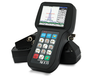
Fig. 1. Appearance of UD3-71 electronic unit
Purpose
UD3-71 — universal ultrasonic flaw detector is intended for:
- manual nondestructive testing of products for the presence of defects, such as discontinuity and inhomogeneity of material in raw stock, end products, semifinished products, welded, soldered, bolt, rivet and other joints;
- measurement of defects depth and depth coordinates;
- measurement of thickness of various items at one-way access to them;
- measurement of signals amplitudes ratios reflected from defects;
- measurement of equivalent dimensions of flaws;
- evaluation of sound velocity in different materials.
Main specifications of UD3-71 flaw detector
| USW (ultrasonic waves) frequency pass bandwidth of flaw detector | from 0,4 to 15 МHz |
| Possible set values of filter frequencies: | 0,4; 1,25; 1,8; 2,5; 5; 10; 15 МHz |
| Values of rated frequencies of initial pulse repetition | from 100 to 1000 Hz with setup resolution 1; 10; 100 Hz |
| Initial pulse amplitude of flaw detector pulser at the duration of (80-20) ns and edge duration of no less than 20 ns | no less than 200 V for the mode of max. initial pulse amplitude, 20 V for the mode of min. initial pulse amplitude |
| Range of gain change of flaw detector reception path | from 0 to 80 dB |
| Resolution of gain change of flaw detector reception path | 0,1; 1,0; 10,0 dB |
| Dynamic range of signals observed on the flaw detector screen | no less than 20 dB |
| Range of testing for defects presence in steel | from 0,5 to 6000 mm with setup resolution 0,1; 1,0; 10,0; 100,0; 1000,0 mm |
| Range of defects depth measurements in steel | from 0,5 to 6000 mm |
| Range of equivalent reflector diameter measurements | from 0,8 to 20 mm |
| Range of sound velocity setup | from 1000 to 15000 m/s with setup resolution 1; 10; 100; 1000 m/s |
| Range of probe angle setup | from 0 to 900 with setup resolution 0,1; 1,0; 10,00 |
| Range of scan delay setup relative to excitation pulse | from 0 to 6000 mm with setup resolution 0,1; 1,0; 10,0; 100,0; 1000,0 mm |
| Range of setup of measuring gate delay length | from 0,1 to 6000 mm with setup resolution 0,1; 1,0; 10,0; 100,0; 1000,0 mm |
| Range of ALARM threshold setup (heights of measuring gate levels): | |
| — acceptance level (red level of gate) | minus 18 — +6 dB, step: 0,1; 1,0 dB |
| — registration level (blue level of gate) | minus 18 — +6 dB, step: 0,1; 1,0 dB |
| — search level (green level of gate) | minus 18 — +6 dB, step: 0,1; 1,0 dB |
| Range of setup of linear compensated cutoff | from 0 to 60 % of the screen height with setup resolution 1 % |
| Number of stored flaw detector setups | no less than 100 |
| Number of stored scan views (А-Scan views) | no less than 100 |
| Number of stored measured depth (coordinates) values | no less than 150 000 |
| Weight of flaw detector with storage battery (without probes set, cables and case) | no more than 0,720 кг |
| Overall dimensions of flaw detector | no more than 188×107×78 mm |
| Size of working area of flaw detector screen | no less than 71,52×53,64 mm |
| Flaw detector is powered from built-in storage battery with rated voltage | 12 V |
| Capacity of built-in storage battery | 2500 mА/hour |
| Average duration of continuous operation | no less than 12 h |
The level of flaw detector case protection from solid bodies and water penetration corresponds to IР65 according GOSТ 14254.
Flaw detector can be operated at the ambient temperature from minus 10 to + 40 °С.
Main modes of flaw detector
Application of modern techniques of digital signals processing provides an undistorted transmission of acoustic signal waveform, high accuracy of measurement of items thickness and defects parameters.
Flaw detector functions manipulation is based on the principle of folded submenus.
Thus, for example, having selected the wanted menu, an operator can activate all necessary parameters, set up the required image brightness or switch on the sound alarm. It should be mentioned that the usage of new up-to-date element base and bright high-contrast color TFT display resistant to direct sunlight and with resolution of 320×240 pixels and visible screen part dimensions of 72×54 mm enabled to perform qualitative modernization of the instrument. That is:
- to get rid of such drawback as screen time lag (such flaw is characteristic of liquid crystal displays) what made it possible to increase the scanning speed while testing;
- To measure the signals parameters, there are two independent measuring gates of ALARM with flaw alarm system (sound and LED) by each gate in UD3-71 flaw detector. With that, every gate has:
- three going off levels: "ACCEPTANCE"; "REGISTRATION"; "SEARCH"; marked on the flaw detector screen in "RED", "BLUE" and "GREEN" colors, corresponding colors of LED alarm by each gate.
- corresponding colors of LED alarm by each gate.
- the level of sound alarm going off is set up by an operator by a certain gate.the mode (when the set level is exceeded or not) is set up by an operator for every gate independently.
This allows to perform the testing for "ensounding" (inspection of bottom signal amplitude) or test the acoustic coupling signal presence simultaneously with the inspection of signals in the testing area.
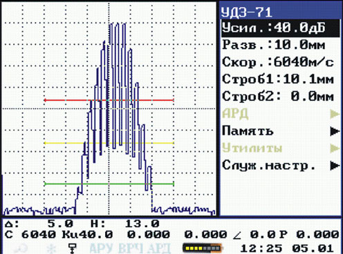
Fig. 2. Three adjusted levels of ALARM going off for one pulse gate
- The existing system of automatic gain control (AGC) can keep the necessary levels of signals during scanning. It is reasonable to use AGC system when setting up the acceptance level of sensitivity by reference signal in the testing object (for instance, by bottom signal). To gate the reference signal during operation with AGC system, a special AGC gate is provided in flaw detector. By changing AGC gate level on the flaw detector screen, one may adjust AGC level, respectively from 25 to 100 %. AGC can also be used for quick measurement of echo signals amplitude relative to AGC gate level.
- The system of time control gain (TCG) is applied for alignment of echo signals by amplitude, for example, for compensation of ultrasound attenuation in the testing object. In UD3-71 flaw detector TCG level is set in the point given by an operator and is linearly decreased in adjacent points which have not been indicated before. Thereby, it is possible to set different shapes of TCG curve — linear, step and etc. TCG level corresponds to the signal attenuation in this point relative to the set gain value.
- When testing sheet items, one may use "REFLECTIONS MARKING" mode, which helps to imagine the detected defect location in the testing item;
- "Still frame" mode is convenient for inspection and registration of А-Scan view. In this regard, there are two signals on the screen: the signal registered in the moment of this mode switching-on (displayed in red color) and the current active signal.
- "Peak" mode is indispensable while searching for small flaws, operating in conditions of unstable acoustic coupling. With that, the current signal value is displayed on the screen together with max. envelope of all observed echo signals (displayed in yellow color). This mode is used for determination of max. echo signal amplitude and estimation of conditional length. It can be applied for the registration of testing results both for rejected and accepted items what will prove the presence or absence of defect over the whole scanning perimeter.
- "Electronic magnifying glass" mode enables to view in detail the wanted echo signal without resetting the scan parameters of flaw detector;
- Distinctive feature of UD3-71 flaw detector is the measurement of conditional defect dimensions.
Fig. 3. AGC gate on UD3-71 display
Fig. 4. TCG curve on UD3-71 display
Fig. 5. "Reflections marking" mode
Fig. 6. Overlaying of "frozen" signal over the current signal
Fig. 7. UD3-71 screen view while operating in "peak" mode
Fig. 8. "Electronic magnifying glass" mode
Using DGS diagrams, UD3-71 flaw detector allows to measure equivalent defects dimensions in the range from 0,8 to 20,0 mm (equivalent defect diameter) with relative error of no more than 15 %.
DGS diagrams, as it is clear from the name (DGS — Amplitude, Distance, Diameter), describes the ratio of echo signal amplitude and disk reflector situated on the acoustic axis of probe and perpendicular to it, and the distance between the prone and reflector and disk reflector diameter.
The application of DGS diagrams in UD3-71 makes it possible to automate the flaw detector setup. DGS diagrams system enables to set up automatically TCG of flaw detector in accordance with DGS diagram for the selected probe. Upon that, the amplitudes of echo signals from defects of the set equivalent area situated at the level set in the acceptance level item — "Acc.lev.". Besides, DGS curve can be plotted for the set equivalent diameter on the flaw detector screen.
Fig. 9. AGC curve on UD3-71 screen
The system of DGS diagrams usage in UD3-71 allows to operate the probes of the following types:
- Straight beam single crystal probes of longitudinal wave;
- Angle beam single crystal probes of transverse wave with frequencies from 1,62 to 5,5 МHz and refracted angles from 36 to 73 degr.
To set up UD3-71 for DGS operation, it is necessary to enter only several parameters of the used probe and perform the instrument calibration by the reference signal from reflector in the test piece, for example, Ø6 mm hole in СО-2, for operation in DGS mode.
Setups with DGS diagrams for specific testing tasks can be stored in the instrument permanent memory.
- The mode of connection with PC is essential to transfer data from flaw detector memory to computer memory and vice versa. This mode is also necessary to transfer "A-scans" and "Files" in PC for creation of reports basing on the testing results or databases. If required, the setups for specific types of testing can be input by the user from PC into flaw detector via built-in USB port. This considerably reduces the time of flaw detector preparation for testing implementation.
- To measure the item thickness and defects coordinates, undetected RF signal is applied what enables to provide the measurement resolution of 0,01 mm. In the instrument there are two modes of point selection on the signal curve. The measurement is performed by this point (automatic and manual modes).
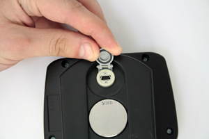
Fig. 10. USB connector on UD3-71 back cover
Fig. 11. "Peak/Edge" measurement modes
In automatic mode the measuring device is actuated by the signal peak or edge.
When operating angle beam probes, flaw detector automatically measures the flaw coordinates with the account taken of probe angle, delay in the wedge and X-value of a certain probe type.
Up to four measured parameters can be simultaneously displayed on the flaw detector screen in the first line of information section:
Δ —deviation of the signal locating in the measuring gate by the amplitude relative to normal level – screen middle;
А —value of gain at which the signal amplitude makes 50% of the screen;
H —defect depth;
X , Y —defect depth coordinates;
De —equivalent defect diameter;
Se —equivalent defect area.
- A wide range of suggested probes with operating frequency from 400 kHz to 15 МHz both for flaw detection and thickness gauging allows to solve a lot of users' tasks. About 48 type names of ultrasonic probes are series-produced for UD3-71 flaw detector operation. UD3-71 flaw detector can be equipped with special-purpose probes for specific testing technology.
- UD3-71 can be successfully applied while testing the base metal thickness of various manufacturing equipment. Visualization of thickness measurement process makes it possible to avoid common errors during its measurement by "blind" thickness gauges.
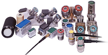
Fig. 12. Probes for UD3-71
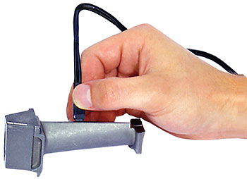
Fig. 13. Measurement of blade wall thickness by UD3-71 flaw detector with the application of P112-10-2×3-004 probe
The instrument body is made of impact-resistant plastic; membrane keyboard is oil- and gasoline-resistant. Keyboard buttons layout and ergonomic body enable to hold and operate flaw detector with one hand what is very important when inspecting cranes and altitude objects, while testing at mounting. Leather cover makes it possible to fasten the instrument on an operator's hand in various ways.
Delivery set of flaw detector includes everything necessary for testing execution. "Prompribor" LLC manufacturer provides the warranty (within 18 months since the delivery date) and post-warranty service of flaw detector. When implementing UD3-71 instrument, "Prompribor" LLC renders assistance on training and retraining of operators for the introduction of modern techniques of ultrasonic testing in manufacture.
Due to the positive results of the State acceptance trials and production tests, UD3-71 flaw detector entered the State register of instrumentation technology admitted for application in Russia.
UD3-71 flaw detector is successfully used at the enterprises of Russia and CIS countries. Thus, in "Gaznadzor" LLC for the determination of technical state of gas distribution stations when inspecting the pipelines under pressure "…UD3-71 flaw detector proved to be a modern instrument with extended base kitting which is an optimal solution for the tasks of inspection by NDT techniques … we recommend to use UD3-71 flaw detector as the main equipment for NDT carrying out on the objects of gas-supply systems, boilers, equipment of oil and gas industry …", — А. Gorlanov, Foreman of engineering supervision and inspection of "Gaznadzor" LLC.
When the specialists of "Echo+" scientific and production centre perform thickness gauging on the objects of Volgodonsk nuclear power station by UD3-71 flaw detector, the following advantages have been singled out in comparison with "blind" thickness gauges:
- possibility of operation on unprepared surfaces;
- visualization of the wall thickness measurement procedure allows an operator to avoid common errors while measuring the wall thickness by thickness gauges only with digital display of results;
- possibility of thickness measurement by the first and second bottom signal (i.e. delay in the probe wedge is not taken into account);
- operation ease./li>
For more than a year the specialists of "Samaracontrolservis" LLC have been operating UD3-71 flaw detectors in different places of Russia (regions of Far North, Samara and Saratov oblasts), both in filed and shop conditions. "…small weight and dimensions of the instrument are an advantage during business trips, and also enable to operate flaw detector in complicated and limited conditions. DGS functions are very convenient to use for the determination of equivalent defect area… UD3-71 flaw detector, as a unit, is rather reliable and convenient-to-operate instrument", – S. Sukhanov, Engineering Director of "Samaracontrolservis" LLC.
Summing up, it is worth mentioning that the staff of our enterprise used its many years' experience in the development of this instrument. We hope that UD3-71 application will allow to facilitate an operator's work and will make the testing max. trustworthy.
A. Svistun
Engineer, "Prompribor", III grade of acoustic NDT techniqu
Categories:
Partners: