UD4-94-ОKО-01 universal ultrasonic flaw detector

PURPOSE
UD4-94-ОKО-01 universal multi-channel ultrasonic flaw detector is intended for products testing for the presence of defects, such as material discontinuity and inhomogeneity of end items, semiproducts and welded (soldered) joints, for the defects detection, the recognition of their forms and orientations, the measurement of depths (coordinates) or conditional dimensions of defects. Flaw detector (as a part of mechanized and automated complexes of non-destructive testing as well) can be applied for the testing of products quality during their production and operation in various branches of industry.
UD4-94-ОKО-01 universal multi-channel ultrasonic flaw detector is adapted and completely meets the requirements of regulatory documentation in force in various industrial sectors, such as:
- nuclear power engineering;
- metal production;
- pipe industry;
- rail transport etc.
FLAW DETECTOR ADVANTAGES
- high performance due to flaw detector multi-channeling;
- possibility of flaw detector implementation when performing mechanized and automated testing;
- exclusion of human factor influence (if it is used as a part of the mechanized testing system);
- flaw detector provides the defect form and orientation recognition, measurement of depths (coordinates) or conditional dimensions of defects;
- operation simplicity due to the intuitive interface;
- registration of all testing results and extended capacities of data analysis;
- application versatility and possibility of any configuration formation of NDT multi-channel system on the basis of flaw detector.
FLAW DETECTOR DISTINCTIVE FEATURES
- large color high-contrast TFT display;
- ALARM system: 4 three-color LEDs, sound alarm;
- various scanning units manipulation;
- RS232 support;
- encoder connection;
- software application for different testing tasks: longitudinal and ring welded joints testing, rolled metals testing, etc;
- any sounding schemes carrying out in automatic and manual modes;
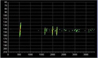
- A-scan display form: Envelope;
- information display forms: А-scan, B-scan, orthogonal views.
TECHNICAL SPECIFICATION AND SERVICE FUNCTIONS OF THE INSTRUMENT
- possibility of the account taken of the real probe location in a scanner for the correct testing results processing during scanners manipulation;
- possibility of the delay time measurement in the probe wedge;
- possibility of the sound velocity measurement in the testing object;
- display of the measured coordinates of detected defects on B-scans and orthogonal views of B-scans;
- mode of max. signal accumulation in А-scan;
- possibility of compact-flash memory device (up to 2 Gb) installation in flaw detector;
- personal computer (PC) connection mode for the information input from flaw detector memory to PC, testing results processing and their printing, setups input from PC to flaw detector memory;
- possibility of testing results storage on the memory device such as compact-flash;
- possibility of the stored testing results viewing directly on the instrument.
PERFORMED CONFIGURATIONS
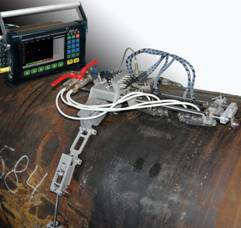
By creating special searching systems or scanners and by reprogramming UD4-94-ОKО-01 multi-channel instrument for a certain testing object, it is possible to carry out efficiently metal production flaw detection technologies in various branches of industry. All in all, UD4-94-ОKО-01 flaw detector complete with scanners is a universal mechanized complex of non-destructive testing.
Today, UD4-94-ОKО-01 ultrasonic flaw detector, together with scanners, solves the following tasks of ultrasonic flaw detection:
- Testing of welded joints of tanks, vessels and other sheet products
- Testing of welded joints of tanks, vessels and other sheet products
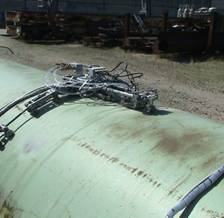
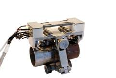
SCL-M portable system of mechanized ultrasonic testing on the basis of UD4-94-ОKО-01 is intended for mechanized ultrasonic welded joints testing of tanks, vessels and other sheet products. The scanner is a mechanized system which provides ultrasonic probes positioning in relation to the welded joint, probe pressing, probe movement along the joint with the guide for welded joint tracking.
- Testing of main pipe body of various dimension-type pipelines
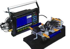
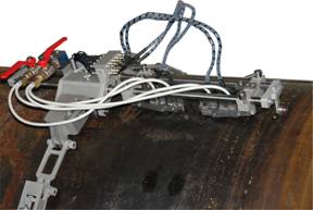
SKТТ-TS scanner on the basis of UD4-94-ОKО-01 flaw detector is intended for performing mechanized ultrasonic testing of the pipe body with diameter of 168 – 355 mm, wall thickness of 5 – 30 mm and length of 4 – 14 m for the purpose of detection of defects, such as longitudinal and transverse cracks and delaminations.
ADDITIONAL SOFTWARE
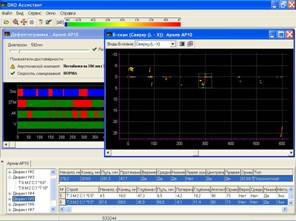
"ОKО-Assistant" program is intended for testing results processing of ОKО-01 universal ultrasonic flaw detector and serves for functionality expansion and instrument usability increase. The present program provides operation with the data stored on the personal computer.
Main advantages of program application are:
- convenient selection of testing schemes and archives for editing and viewing with the preliminary file information display;
- creation of new and editing of the existing instrument testing schemes with the checking of the input setups admissibility;
- input and storage of rejection criteria in the testing scheme;
- multi-channel interface allowing to work with several testing results (archives) at a time;
- flexible selection of various archives viewing types, including display of "raw" B-scans, B-scans projections and defectograms (B-scan, C-scan, D-scan);
- zooming, preset area increase, convenient diagrams scrolling;
- rejection criteria application on the basis of adjustable compound rejection condition;
- testing reliability indices calculation;
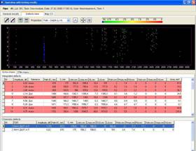
- creation of a total table of testing results 3D-defects;
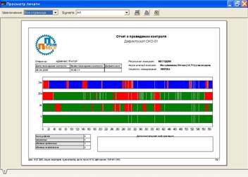
- printing of ultrasonic testing report on the basis of an overall defectogram;
- printing of a table of 3D-defects and its component "planar" defects, and also printing of separate ultrasonic testing results: B-scans, projections;
- availability of the users list with the password system and possibility of access rights limitation.
| Main specifications | |
| Overall dimensions of flaw detector without a handle and with one ultrasonic unit and power unit | no more than 320×180×140 mm |
| Weight of flaw detector with one ultrasonic unit and power unit | no more than 6 kg |
| Keyboard | English, Russian |
| Languages | English, Russian |
| Number of ultrasonic units | max. 3 |
| Number of ultrasonic channels in ultrasonic unit, no more than | 32 |
| Connectors types | Lemo-00, BNC |
| Data storage | flash card |
| Independent power source | NiMH storage battery of rated voltage 12 V and rated capacity 9 А∙h |
| Operation time (when powered from storage battery) | 8 hours |
| Power supply | AC mains of voltage (from 187V to 242V) and frequency (50 ± 1) Hz; |
| Flaw detector electric power consumed from AC mains | no more than 30 V·А |
| Time of flaw detector operation mode setup | no more than 10 min |
| Display type | NL8060BC21-03 (800×600 pixels) |
| Screen dimensions (width, height, diagonal) | 170 mm × 130 mm, 214 mm |
| Warranty | 1 year |
| Interfaces | |
| RS – 232 | available |
| Trigger I/O | available |
| Encoder output | single-coordinate encoder |
| Main metrological performances | |
| The limits of admissible main absolute error of flaw detector during the measurement of depth dН and coordinates |
|
| П The limits of admissible main absolute error during the measurement of signals amplitudes ratio ∆N at the reception path input in the gain range from 20 dB to 70 dB | ∆N = ±(0,2+0,03N)
∆N - main absolute error during signals amplitudes ratio measurement, dB N - numeric value of signals amplitude ratio, dB |
| Time instability of flaw detector reception path sensitivity | ± 0,5 dB for 8 hours of continuous operation |
| Protection level in operation | IP 64 |
| Ambient temperature | from minus 10º to +40ºС |
| Atmospheric pressure | from 84 to 106,7 kPa |
| Relative humidity | (93 ± 3) % at the temperature 25 ºС |
| Flaw detector in shipping package is resistant to the influence of |
|
| Flaw detector retains its parameters when it is influenced by electromagnetic interferences which do not exceed the following norms |
|
| Full average flaw detector lifetime | no less than 10 years |
| Probability of no-failure operation | no less than 0,9 for 2 000 h |
| Pulser | |
| Initial pulse type | short pulse of negative polarity |
| Initial pulse frequency | from 10 Hz to 1000 Hz with a step of 1, 10, 100 Hz |
| Amplitude | 180 V |
| Duration | 60±10 ns |
| Rising edge duration | no more than 20 ns |
| Synchronization type | from initial pulse, from encoder |
| Receiver | |
| Gain | from 0 to 100 dB with a step of 0.1, 1, 10 dB |
| Input signal | no more than 2 V from a peak to a peak |
| Input reception path resistance | no more than 300 Ω |
| Pass band | from 0.4 to 10 MHz at the level – 6 dB |
| Rectifier | radio frequency, envelope |
| Setups mode | |
| Automatic setups |
|
| Measurements | mm, µm |
| Testing range | from 0 to 18000 mm, with a step of 0.1, 1, 10, 100 mm at the sound velocity of 6000 m/s |
| Velocity | from 1500 m/s to 8000 m/s, with a step of 1, 10, 100, 1000 m/s |
| Delay in a wedge | from 0 to 100 µs, with a step of 0.001, 0.01, 0.1, 1 µs |
| Range delay | from 0 to 6000 µs, at the velocity of 6000 m/s, with a step of 0.1, 1, 10, 100 µs |
| Refracted angle | from 0 to 900, with a step of 10, 100 |
| Cycles/gates | |
| Cycles amount | max. number of cycles 32 |
| Cycle duration | min. cycle duration 0.2 ms |
| Number of gates in a cycle | max. number of gates 3 |
| Beginning of a gate | from 0 to 3000 µs, with a step of 0.1, 1, 10, 100 µs |
| Gate width | from 0 to 18000 mm, with a step of 0.1, 1, 10, 100 mm at the sound velocity of 6000 m/s |
| Gate fixation level | from 10 % to 95 % of vertical screen scale |
| ALARM | when the signal goes beyond the fixation level, when the signal stays within the fixation level |
| Measurements in A-scan mode | |
| Displayed parameters | 4 measuring parameters are displayed in a status bar |
| Gate 1 |
|
| Gate 2 | similarly to Gate 1 |
| Gate 3 | similarly to Gate 1 |
| TCG curve | max. number of points 30 per cycle, dynamic range no more than 35 dB, vertical setup step 1 dB, horizontal setup step 2 mm |
| Measurements in B-scan mode | |
| "Raw" B-scan |
|
| Corrosion map |
|
| "Corrosion map" mode |
|
Categories:
Partners: